E-mail: sale@xxdahan.com
Follow Us 


A precision electroformed micro sieve is a high-accuracy analytical sieve manufactured via photolithography and pure nickel electrodeposition.
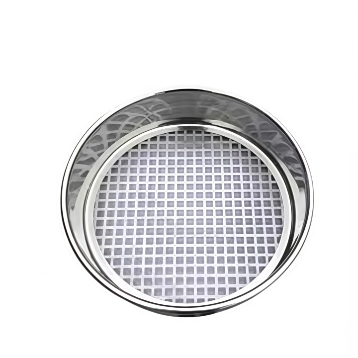
Its aperture tolerance can be stably controlled within ±1 to ±2 μm. The mesh surface is mirror-smooth without the intersecting junctions found in traditional woven wire screens.
Before selection, clarify when an electroformed sieve is necessary and when a conventional woven sieve suffices, by comparing the key parameters below.
| Comparison Dimension | Precision Electroformed Micro Sieve (Electroformed) | Traditional Metal Woven Wire Sieve (Woven Wire) |
| Processing Technology | Photolithography + Pure Nickel Electrodeposition | Mechanical Weaving of Metal Wire |
| Common Aperture Range | 2 μm to 500 μm | Generally greater than 20 μm |
| Aperture Tolerance Accuracy | ±1 μm to ±2 μm | Complies with ASTM E11 / ISO 3310-1 |
| Mesh Surface Flatness | Completely flat, no cross knots | Raised wire interweaving |
| Probability of Plugging and Powder Sticking | Extremely low | High |
| Typical Application Scenarios | Sub-micron fine powder analysis, 3D printing metal powder | Conventional particle screening, coarser powder classification |
Aperture is the core basis for sieving and classification, and tolerance accuracy directly affects the reliability of powder test results.
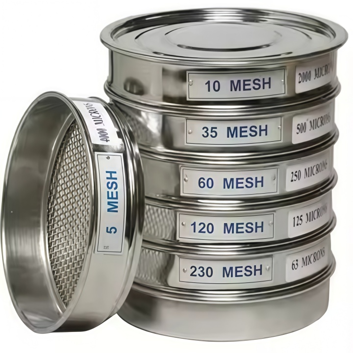
Precision electroformed micro siev can achieve a tolerance of ±1 μm. For fine analysis, select products complying with the tolerance requirements of ASTM E161 or ISO 3310-3.
Aperture shape affects particle passage, while the open area ratio balances sieving efficiency and mesh strength.
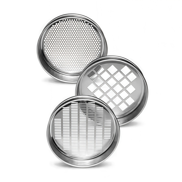
Square holes: Most widely used and the first choice for standard particle size testing.
Round holes / elongated holes / hexagonal holes: Suitable for particles with special flow characteristics or elongated shapes.
Open area ratio: The smaller the aperture, the thicker the supporting metal walls, resulting in a lower open area ratio.
Materials and dimensions of the mesh and sieve frame shall match your material properties and the interface of your sieving equipment.
| Component | Optional Configuration | Feature Description |
| Sieve Surface | 99.9% Pure Nickel | Corrosion-resistant, good dimensional stability, not easily deformed |
| Sieve Frame | 304 Stainless Steel / 316L Stainless Steel | Suitable for conventional working conditions and corrosive working conditions |
| Sieve Frame | Acrylic | Transparent version, convenient for real-time observation of the screening process |
| Sieve Frame Specification | 3 inch (75 mm), 8 inch (200 mm), 12 inch (300 mm) | Compatible with different models of sonic sieve analyzers and vibrating sieve machines |
Whether to use a support grid is determined mainly by aperture size and sieving method to protect the mesh from damage.
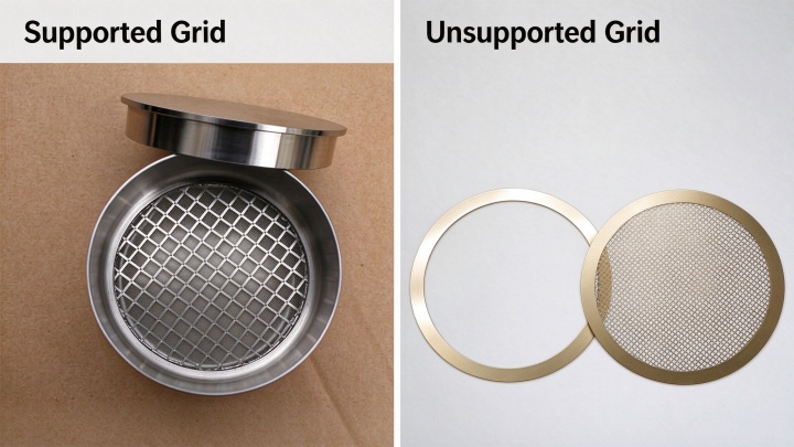
With support grid: A coarse reinforcing rib grid is added under the microporous mesh as a skeleton. For ultra-fine apertures (e.g., below 20 μm), the mesh is extremely thin. A support grid is strongly recommended to prevent rupture caused by airflow or powder impact.
Without support grid: No obstruction, offering the highest light transmittance. Suitable for specific sonic sieving or optical analysis under a microscope.
For precision powder testing, the compliance and traceability of test data are critical. Confirm applicable standards and calibration certificates during selection.
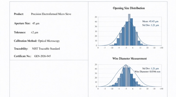
ASTM E161 and ISO 3310-3: When purchasing laboratory electroformed sieves, verify compliance with these two standards, which specify clear requirements for aperture uniformity and dimensional tolerance.
NIST traceability and single-aperture calibration certificates: High-end particle size analysis usually requires factory calibration certificates. Manufacturers typically sample-test aperture dimensions with an optical profile projector or verify with calibration spheres to ensure data is traceable to NIST standards.
The sieving method should be chosen according to powder characteristics and particle size. Proper matching between equipment and process avoids mesh clogging and particle agglomeration for stable and reliable test results.
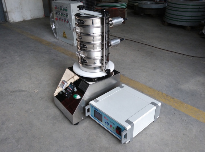
Sonic sieving: Ultra-fine powder tends to agglomerate due to static electricity. Ordinary mechanical sieve shakers cannot work effectively. A sonic sifter is recommended. It disperses powder by air column oscillation and delivers optimal performance with electroformed sieves.
Dry sieving vs wet sieving: For powders smaller than 20 μm, dry sieving often causes severe adhesion. Wet sieving is recommended. Add an appropriate amount of anhydrous ethanol or dispersant to suspend particles in liquid for passage through the micropores.
Precision electroformed micro sieves may not suit harsh test environments. Custom configurations are available according to operating conditions.
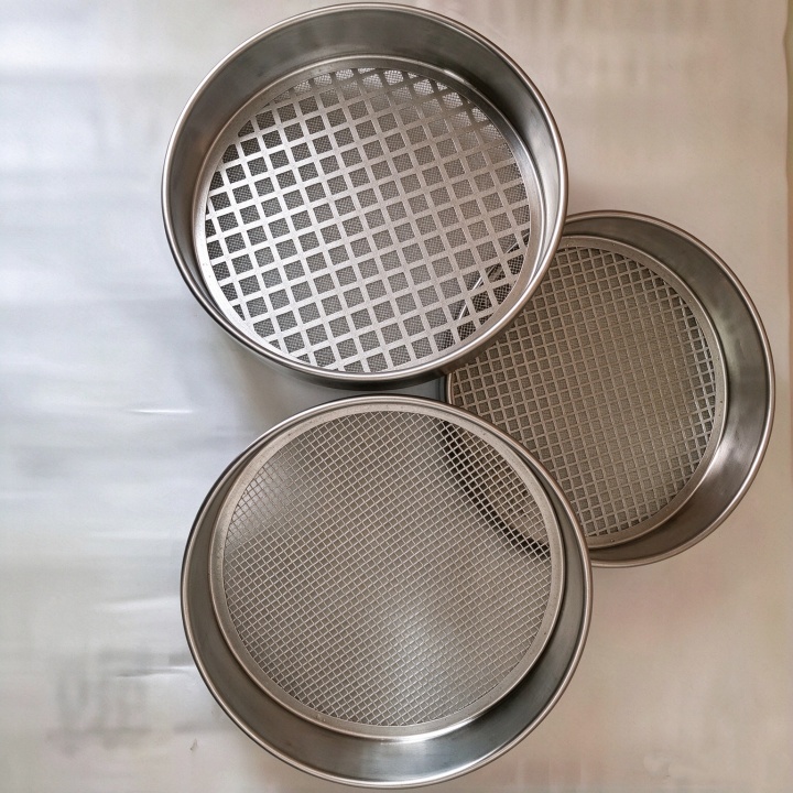
Custom aperture size and pattern: Special experiments may require non-standard aperture sizes or asymmetric hole arrangements.
Special edge sealing and anti-static sieve frames: For highly corrosive or high-static environments, the joint between mesh and frame can be reinforced with epoxy resin or welding. Anti-static frame materials are also optional.
| Step | Selection Operation Key Points |
| 1 | Confirm the particle size of the powder to be tested, and use this to determine the sieve aperture |
| 2 | Select the hole shape based on particle shape; square holes are preferred for conventional testing |
| 3 | Based on the aperture size and screening operation intensity, determine whether a support mesh is required |
| 4 | Measure the interface dimensions of the existing sieve shaker, and select the appropriate sieve frame diameter and material |
| 5 | Confirm project requirements and determine whether an NIST traceable test certificate is required |
Pitfall 1: Choosing unsupported mesh for small apertures. Under intensive dry sieving, ultra-thin microporous mesh will rupture quickly. Always prioritize supported grids for small apertures.
Pitfall 2: Performing dry sieving without addressing static electricity. Powders below 10 μm easily stick to the mesh. This is often mistaken for wrong aperture size, while sonic or wet sieving is actually required.
Pitfall 3: Mismatched sieve frame dimensions. 3-inch and 8-inch frames fit completely different sieve shakers. Always check the tray size before ordering.
Q: When testing ultra-fine powder, should I choose square holes or round holes?
A: Square holes are sufficient for most standard particle analysis. They have a larger open area and higher sieving efficiency. Round holes are only needed when particles are irregular (e.g., needle-shaped) and the standard requires measurement of the minimum cross-sectional diameter.
Q: What frame size fits a standard sonic sifter?
A: Most standard sonic sifters are designed for 3-inch (approx. 75 mm) sieve frames. 8-inch (200 mm) frames are intended for larger vibrating sieve equipment.
CONTACT
WhatsApp:+86 18339211009
Email:sale@xxdahan.com
Add:China, Henan Province, Xinxiang City.Yanjin county forest park gate to the west 1000 meters north road